Click to see full resolution version.
The Show
Every year Intel® holds a conference for its Sales and Marketing Group known as ISMC. Over the course of several days, attendees get hands on with Intel’s latest products, meet with Engineers, take training classes, and attend keynotes from company executives.
Being the one major face-to-face event each year for the global sales force, the conference is a big to do. For ISMC 2012, Intel Studios [1] was asked to create a video unlike any we had produced before [2].
The Project
One of the recurring keynotes at ISMC is given by the head of the manufacturing division of the company; giving the audience a look at the innovation and engineering behind the products they sell, as well as a glimpse at the company’s roadmap for the coming years.
Presenting for ISMC 2012 was Executive Vice President and Chief Operating Officer Brian Krzanich; one of Intel Studios’ regular customers. Over the years we’ve created a number of products to accompany his presentations, both internally and externally.
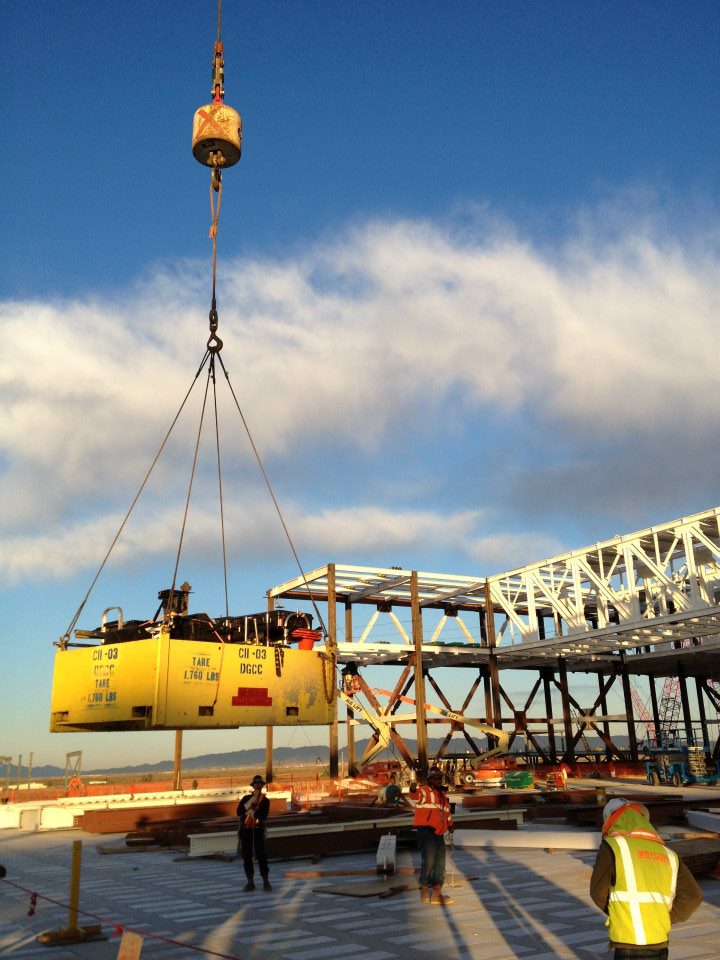
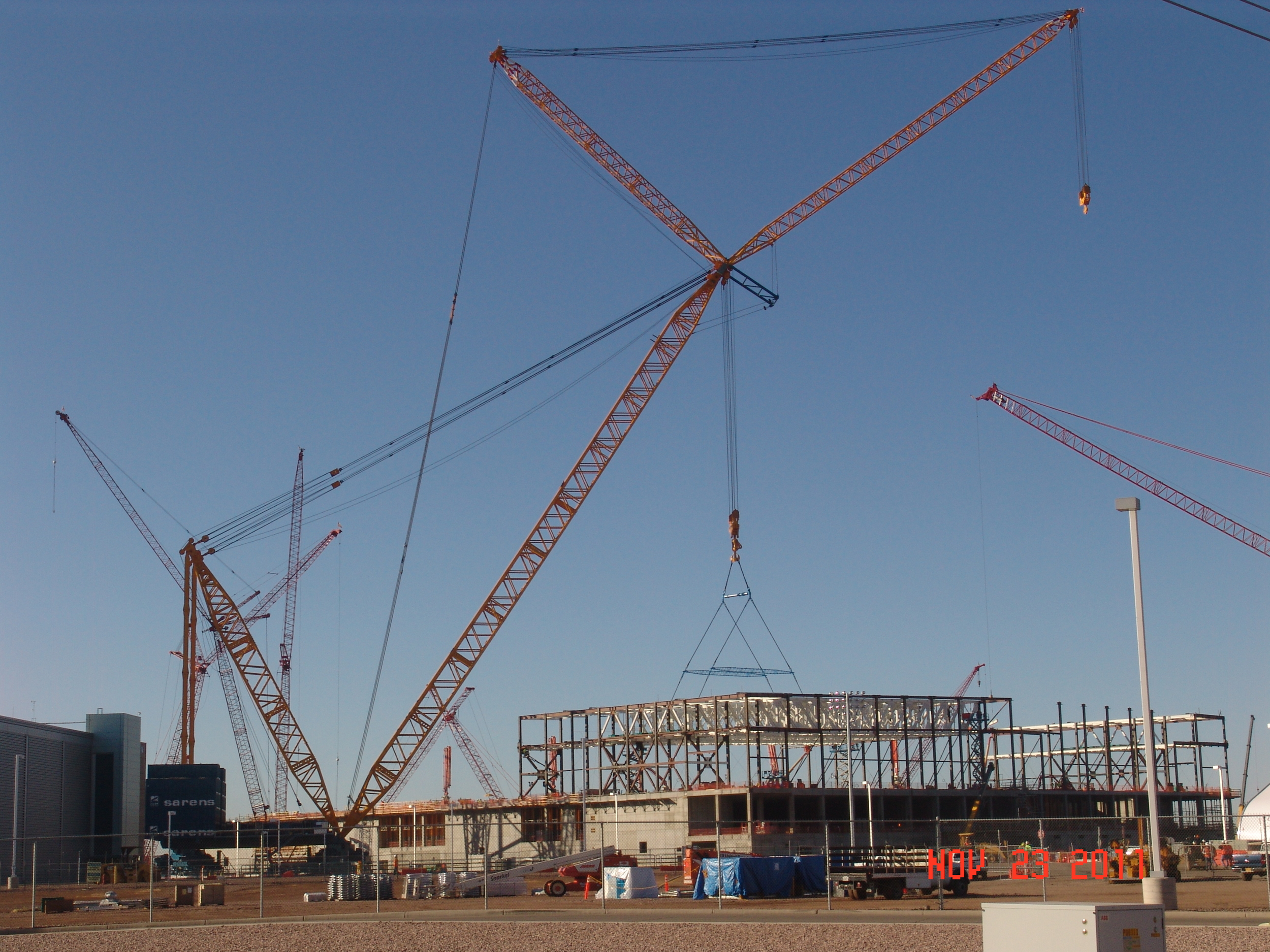
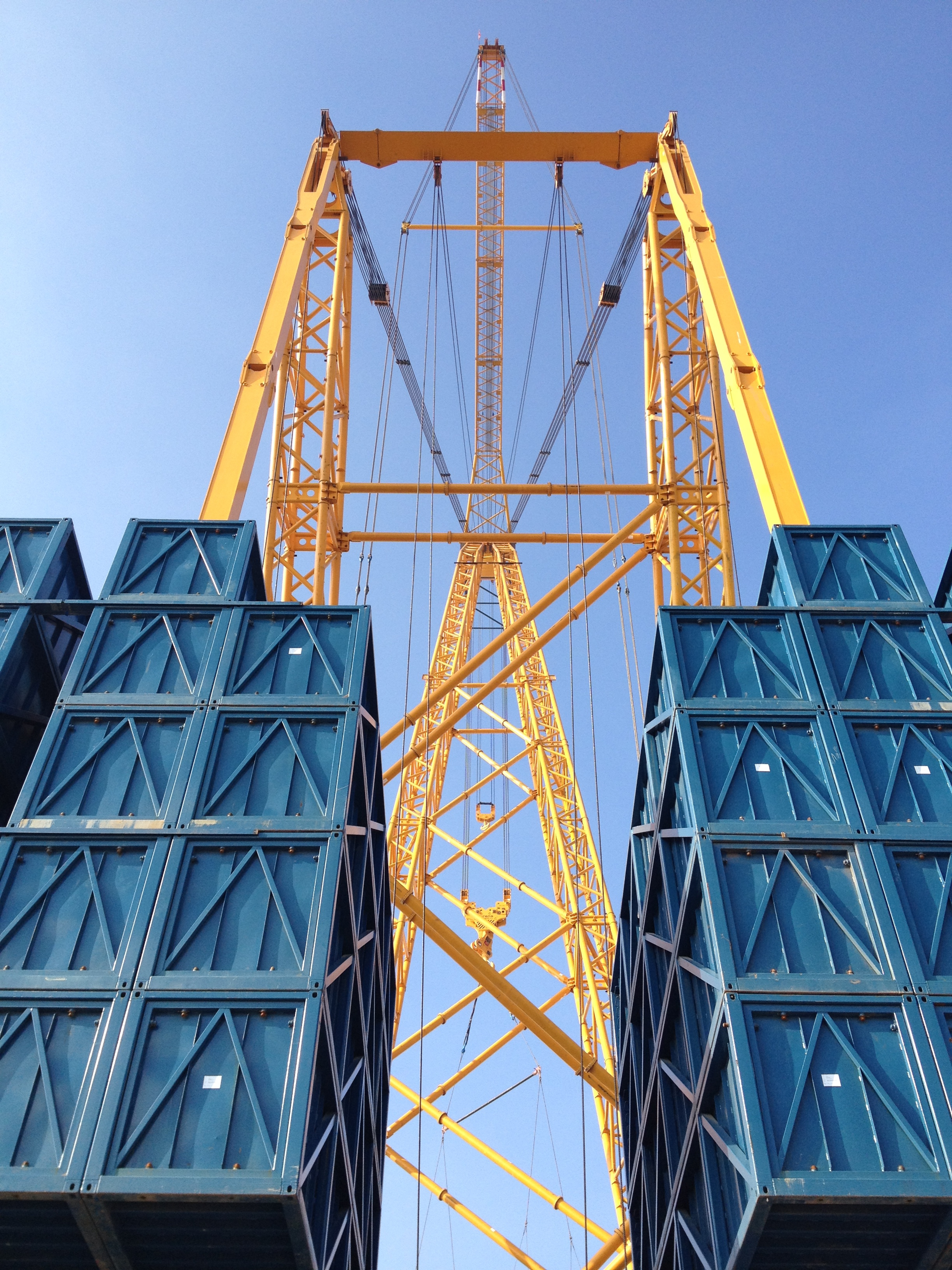
For 2012, the project request was straightforward. Intel was in the process of building two identical manufacturing facilities in Arizona and Oregon, at a cost of around $5 Billion each. The factories represent the state of the art for semiconductor manufacturing [3], but more importantly they are two of the largest cleanroom facilities in the world.
Our job was to highlight the massive scale of these new factories, larger than any Intel has built before, required to make microprocessors at a scale smaller than ever before. The two factories being built were identical, so since our studio was located in Arizona, and production was to take place in December, the Arizona factory was chosen as our subject.
With little more direction than that, we began to develop a story for the video. During concept development we discussed a number of ideas for emphasizing the enormous size of the construction project with the appropriate amount of “wow factor”. Our answer came in the form of the video’s playback venue.
The Venue
The keynote presentations were set up with three projector screens above the stage that would be used together as one large, contiguous display. The combined screen measured nearly 160 feet wide, with a resolution of 7,360 x 1,080; more than twice the width of a standard cinema screen. With a display of such unique proportions, it was an easy decision to shoot panoramic video that would span all three screens, rather than create a collage of separate images to fill the space.
It was sure to be an incredible viewing experience, but within that opportunity was a major technical hurdle for the production team. At the time of production, no single camera existed that was capable of capturing an image of the required resolution. Still, we knew this was an avenue we wanted to pursue, and preproduction for a panoramic video began.
As we were discussing technical solutions to our resolution problem, it was suggested that we shoot with a single Red Epic camera, with a resolution of 5,120 x 2,700, and scale up the final image to fit the screen. While this would have been the easiest solution to implement both on set and in post, it failed the selection criteria for two reasons.
First, the image would be scaled to more than 140% of its original size, compromising the clarity of the final image. And even if a 140% blowup provided an acceptable level of quality, the math is not quite so simple. The Epic has a 5K Bayer pattern sensor that produces a measurable resolution closer to 4K. If we treat the Epic as a 4K camera, we’d be looking at a blowup closer to 180%. With a viewing distance between 30 and 200 feet in the auditorium, the quality loss may have been imperceptible to the audience, but the bigger issue was one of sensor size and optics.
To highlight the size of the factory and take full advantage of the massive screen size in the auditorium, we needed to shoot images with a large Field of View (FOV). The FOV of a given image is determined by a combination of the lens’ focal length and the size of the camera’s sensor [4]. Since there were practical limitations to the focal length of the lenses we would use (more on that in a moment), the only way to create an increased FOV was to increase the width of our sensor. Since we can’t change the actual sensor in the camera, we would need to find a way to combine multiple cameras, each with their own Super–35 sized sensor [5], to simulate a larger sensor camera.
Camera Selection
Now that we knew our solution would involve multiple cameras and wide angle lenses, we started crunching numbers to see which lenses we would use and how many cameras we would need. We could have easily satisfied the technical requirements for projection with two Epics, but we opted to use three cameras for a few reasons.
The first reason was this idea of a simulated large sensor camera. With a two camera solution, we’d need to use the widest possible lenses to properly capture the subject; the factory. The use of extreme wide angle lenses would give us a great deal of optical distortion around the edges of the frame and make postproduction very difficult when attempting to stitch the cameras together. Since we’d have essentially zero time to test just how much distortion would be too much, the safer choice was to use longer lenses on three cameras. Not to mention that using two cameras would place the stitch seam right in the middle of our final image. If there was any slop in the composite, there would be nowhere for our mistakes to hide. So, while we came prepared with a set of Tokina 11–16mm lenses, the widest focal length we used was around 25mm on two Red 18–50mm lenses and one Red 17–50mm.
On that note, we had initially hoped that postproduction would be as simple as hiding the seams of our final image in the small gaps between the three playback screens. However, during a preproduction meeting, we were informed that the center screen would be a good deal wider than the side screens, requiring us to deliver a seamlessly stitched image under the assumption that the seams would be on screen. Starting with a roughly 15K raw image gave us the ability to adjust the overlap between the three cameras based on the objects in the scene and the varying amount of parallax between the foreground and background objects; something that we would learn on set was extremely important for creating successful images.
Testing
After selecting the Epic as the camera for this job, we immediately requested three days of camera rental to test our yet-unproven design for the camera platform. Building an effective camera rig from scratch in under a week is a difficult task when it doesn’t involve multiple cameras.
As with most decisions involving money, it would take several days for us to receive an answer. With the start of production mere days away, there was no time to waste. Using what we had in the studio, we grabbed three Canon T3i DSLRs, some small tripod ball heads, and a cheese plate to create a proof of concept camera rig.
With no idea how best to align the three cameras, we created two proof of concept rigs; one to test correcting a vertical disparity between camera sensors and one to test a horizontal disparity. It was clear from the moment we turned on the cameras that the vertical rig was unusable, so on we went with our design of the horizontal rig.
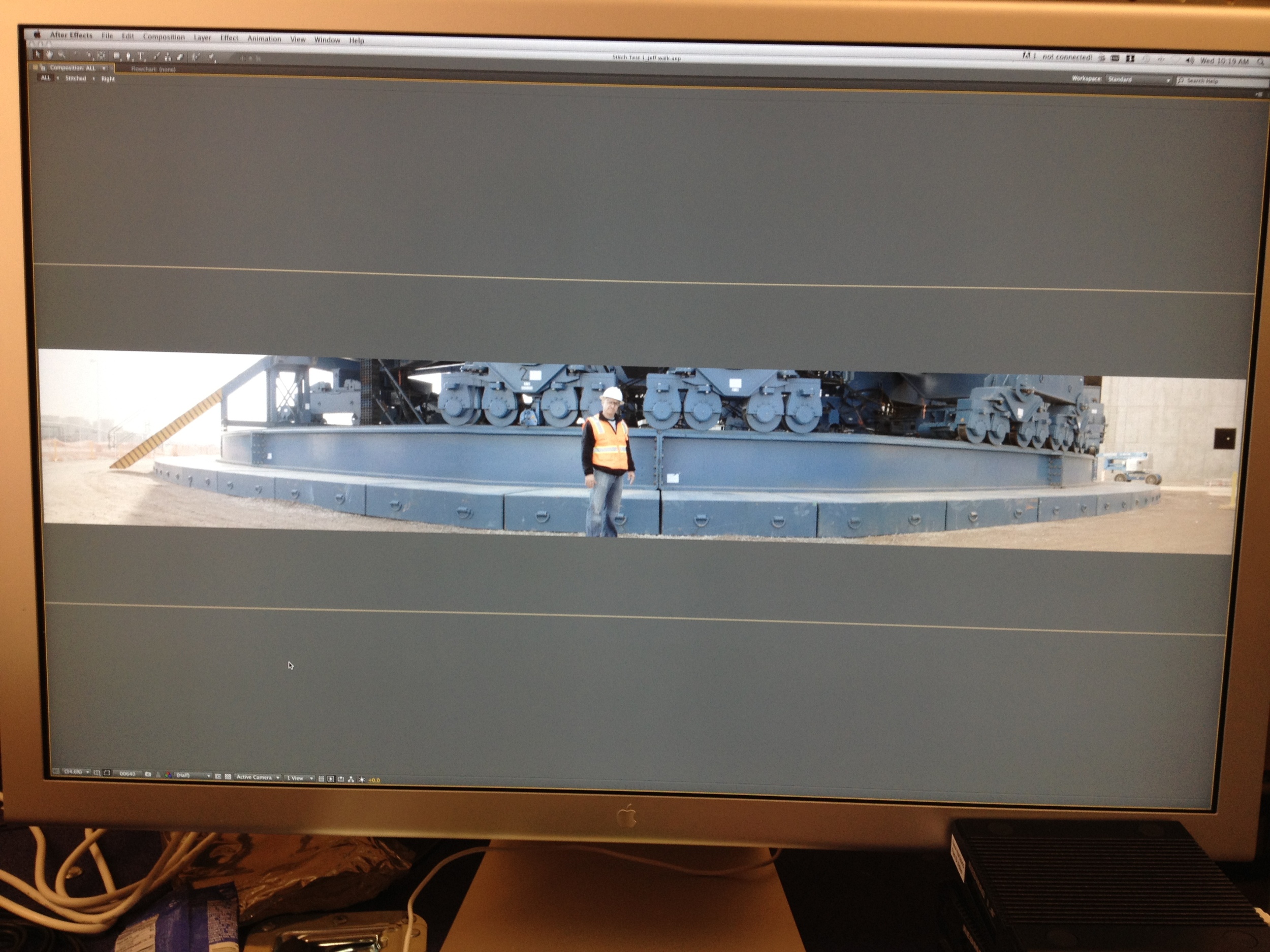
We set up the camera rig outside, near a corner of our office building, giving us a wide view of two sides of the building, the parking lot, and the street. Our primary concern for the stitching process was correcting the parallax discrepancies created by the physical separation of the cameras so, in the test footage, we had a person walk through all three frames, at a variety of distances from the cameras, to see how much error we would encounter in the stitching process. From there the footage was brought into Adobe AfterEffects, synced and aligned.
We determined we were able to stitch and sync the cameras to a relatively high level of success in just a few minutes but, as predicted, the camera separation caused serious parallax discrepancies that had to be corrected with shot-specific compositing. In our test footage, we got a successful panoramic image not by aligning the building that spanned all 3 cameras, but by ensuring that alignment was accurate at the object on which the viewer was focused. In this case, we had to ensure accurate alignment on the person crossing the screen and get creative with hiding misalignment in the background.
The aligning and stitching process felt surprisingly similar to Stereoscopic 3D postproduction we had completed for the 2011 ISMC Keynote [6] where we would ensure elements on the convergence plane were aligned perfectly, and would work around errors in the distant background or close foreground.
A major misstep in our testing process that would come back to bite us later was our failure to test camera movement. The final product was scripted to include pans, tilts, and jib moves, but we were in a hurry to report back to the production team as to the camera platform’s technical feasibility. We attempted to modify a tripod to accept our cheese plate camera platform, but it was clear from our lack of available hardware and materials that in order to test a moving shot we’d have to push back testing at least a day. After an hour of fruitless experimenting with the tripod, we gave up and decided to shoot the test static, propping up the rig on some apple boxes.
After shooting the tests, we spent the rest of the day trying to stitch the images, hiding seams and parallax errors. Just as we began to feel comfortable with the process that would be required, we received word that there was not enough money in the budget to test the real camera setup with Epics.
Building The Rig
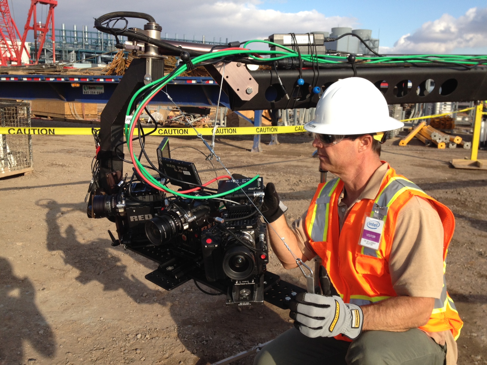
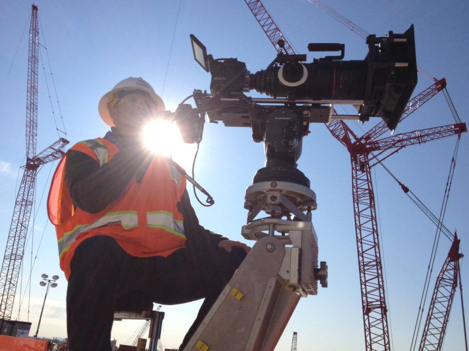
By now it was Friday and production was set to begin on Monday. Two of our three rental Epics had arrived, along with a variety of cheese plates and assorted hardware. We spent the day gathering the rest of the production gear and laying out potential designs of the camera platform.
The first incarnation of our camera platform was built as small as possible to keep the cameras close together and minimize overall weight, but after seeing how much the metal flexed under the fully built rig, we realized larger and thicker cheese plates would be required. We also benefited from using larger plates in our ability to slide the cameras forward and backward on their dovetails, giving us greater balance control over the more minimalist rig.
On Saturday the production team gathered in our studio to build what would hopefully be our final camera platform. We had our jib operator bring his gear so we could make sure our solution would mount properly to his equipment. The majority of the day was spent drilling into the cheese plates so we could countersink the large bolts that were necessary to hold the pieces together.
The addition of a small plate and some angle-iron on the far side of the platform allowed us to attach a support cable to the arm of the jib, taking the weight off of the delicate motors and reducing the amount of bounce to the system. We wouldn’t find out for another couple of days, but it sure looked like we had a camera rig that was going to work.
Just like every other step of the project, we documented the rig building process with our iPhones. When we had the cameras up and running, I posted two photos of our setup on Twitter.
The next day, I received a response from a gentleman names Zac Crosby that included a picture of a panoramic rig built with Epics that he had recently used for a project. His rig was different than ours, built in an almost cube shape with a larger angle between the cameras than we had chosen. It seemed as though Zac’s rig was built to serve a purpose different than ours, but our optimism was re-energized by the idea that we were not the first to attempt such a thing. Especially in light of the (completely unfounded) assumption that if his project had suffered some catastrophic failure, he would have cautioned us about shooting panoramic video.
Lens selection
Since we had to place our gear order before we had a rig design, we took our best guess at which lenses we would need. Being that our goal was to create a massive wide angle image, we ordered three Tokina 11–16mm PL mount lenses, as well as two Red Zoom 18–50mm lenses to supplement our own Red Pro Zoom 17–50mm lens.
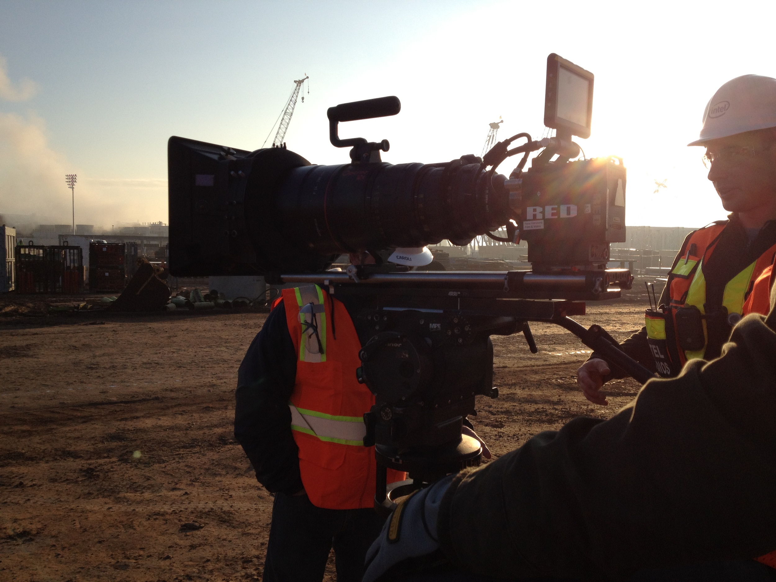
To mitigate some of our risk, not every shot in the video was to be shot panoramic. There would also be instances of collages made up of multiple images, so we brought along our Red Pro Primes, as well as an Angenieux Optimo 24–290mm zoom.
When we finally got lenses on the cameras, we determined a focal length between 20mm and 40mm gave us the best balance of a wide FOV, minimal lens distortion, and enough overlap to properly stitch the shots.
For the majority of the shoot, all three cameras were sporting the Red Zoom lenses. Since we already owned a Red Pro Zoom 17–50mm lens, we only rented two more zooms. In our search for local rental gear, we were only able to find the older 18–50mm Red Zooms. Having never put the updated model side-by-side with its predecessor, we were unaware of the dramatic differences in optical distortion between the two.
The mismatched distortion turned out to not be a problem, but due to our inability to properly test the camera setup, it wasn’t discovered until we began to stitch dailies on set and found undistorting images was not producing expected results. A potential disaster, averted by sheer luck.
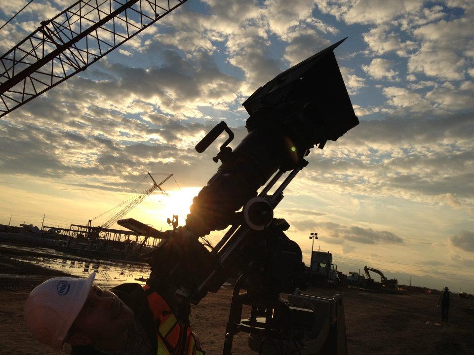
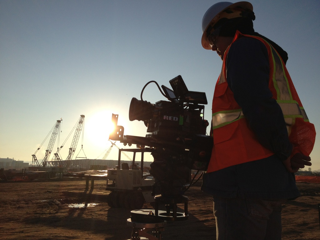
On Set
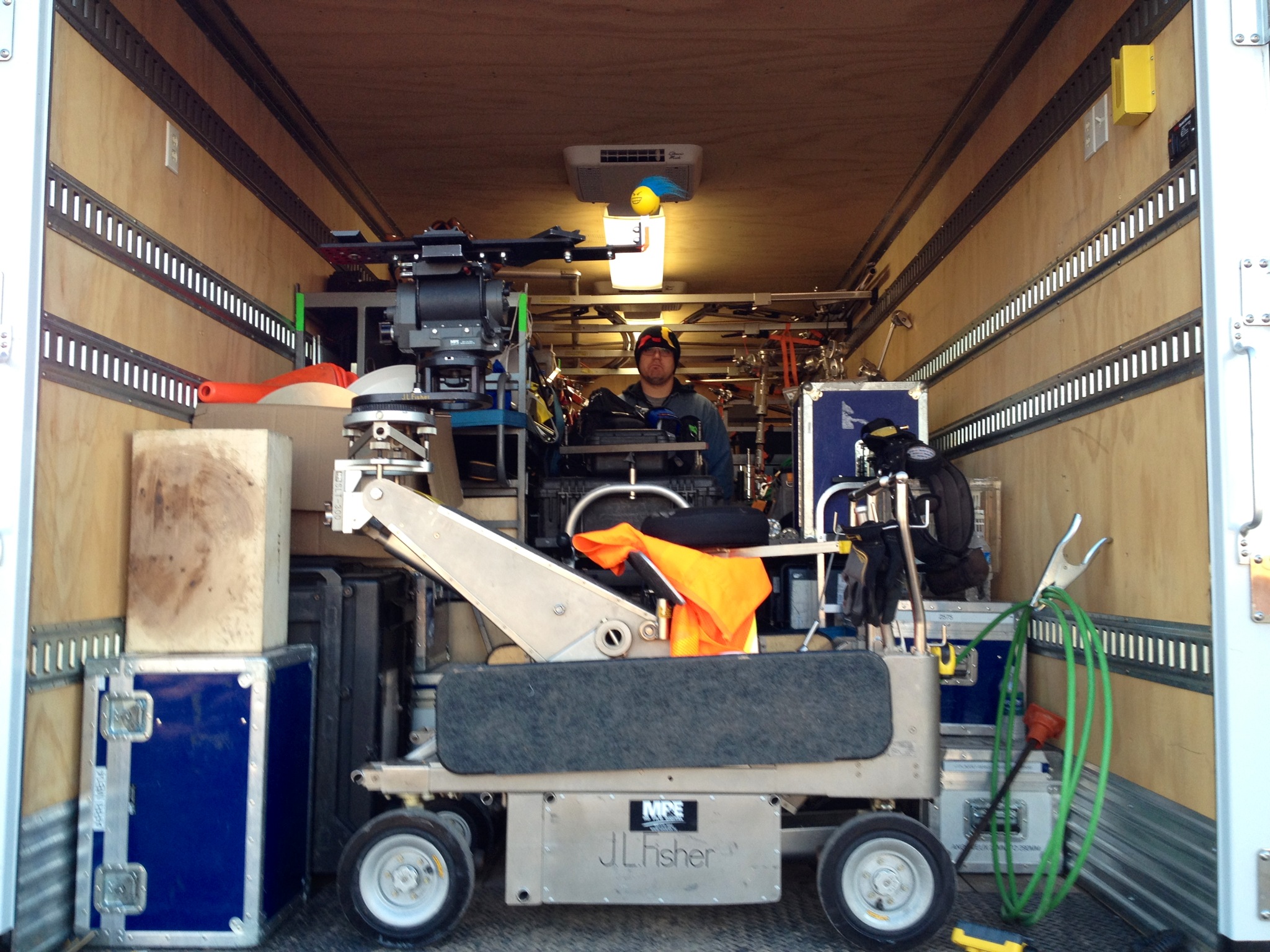
Monday morning started with a lengthy safety briefing from our site escorts before driving our grip truck, with DIT station inside, onto the heavily guarded construction site.
Once inside, we built our camera rig on the jib. We brought along a Fisher 10 dolly, but it was mostly used as a building and transportation platform for the camera rig before transferring it to the jib for shooting. The dolly was also used, to a lesser degree, for one-off static shots between setups. It was the last thing loaded onto the truck and the first thing off, so we occasionally rolled it to the edge of the lift-gate and picked off a few shots from an elevated position.
The cameras were set to record in 5KFF (to take full advantage of the sensor’s FOV) at 24fps and a compression of 6:1. As is often done on shoots involving multiple cameras, each camera, its associated accessories, and magazines were color coded to avoid confusion. A small effort that greatly helped speed up downloads and dailies.
Once we had the jib operating on a live set, we immediately noticed that any tilting of the camera platform caused the left and right cameras to dutch severely. Obvious in retrospect, as all three cameras were rotating on a different axis to their focal plane.
Since our time on the construction site was limited, redesigning the camera platform was not an option. Instead we had to limit our camera movement to booming up and down.
We discovered another limitation of the camera rig while attempting to swing the camera from left to right, following our talent, and booming up over a large mound of dirt to reveal the construction site. Since our talent and dirt hill were about 20 feet from the camera and the construction site was about 200 yards away, our parallax was irreconcilable and, due to the horizontal movement of the jib, there was nowhere to hide the seams should we try to hack the shots together.
After declaring the setup unusable, it was recommended that we either reshoot the scene, limiting the camera move to a simple boom-up, or we spend an unknown amount of time in post separating and completely rebuilding the shot in VFX, to an indeterminable level of success. As with production, our post timeline was extremely limited so we opted to reshoot the scene the next day.
Once we understood the rig’s limitations, the production proceeded relatively smoothly. The only hiccup occurred when one camera’s dovetail came loose in transit, causing the camera to do a backwards somersault off the jib onto the ground. Luckily the jib was only about 12 inches off the ground and the camera landed squarely on the Red Touch 5.0 LCD. The camera was unharmed, and the LCD was perfectly functional, but the metal swivel near the lemo connection snapped and the frame of the LCD was scuffed [7]. The Epic, though, is a tough camera and we were back up and running in a matter of minutes.
Since we knew we would need to undistort the images from each camera in order to stand a chance at stitching them together, we created several 24’’ x 36’’ checkerboard grids on foam boards that were recorded at the beginning of each setup.
Our inability to test the rig in preproduction also resulted in one of our more clever solutions for syncing the cameras. We had neither the cabling nor the knowledge to properly timecode sync three Epics. Our solution involved placing our 24’’ x 36’’ foam lens distortion grid about 4 inches away from the center camera so it was just barely visible on all three cameras at the same time. When the card was in place, someone would flash a DSLR flash against the white board, causing a flash-frame on all three images. It didn’t give us perfect results, and sometimes we had to flash the board twice since the shutters on each camera were not synced, but it was effective enough to give us a useful sync point.
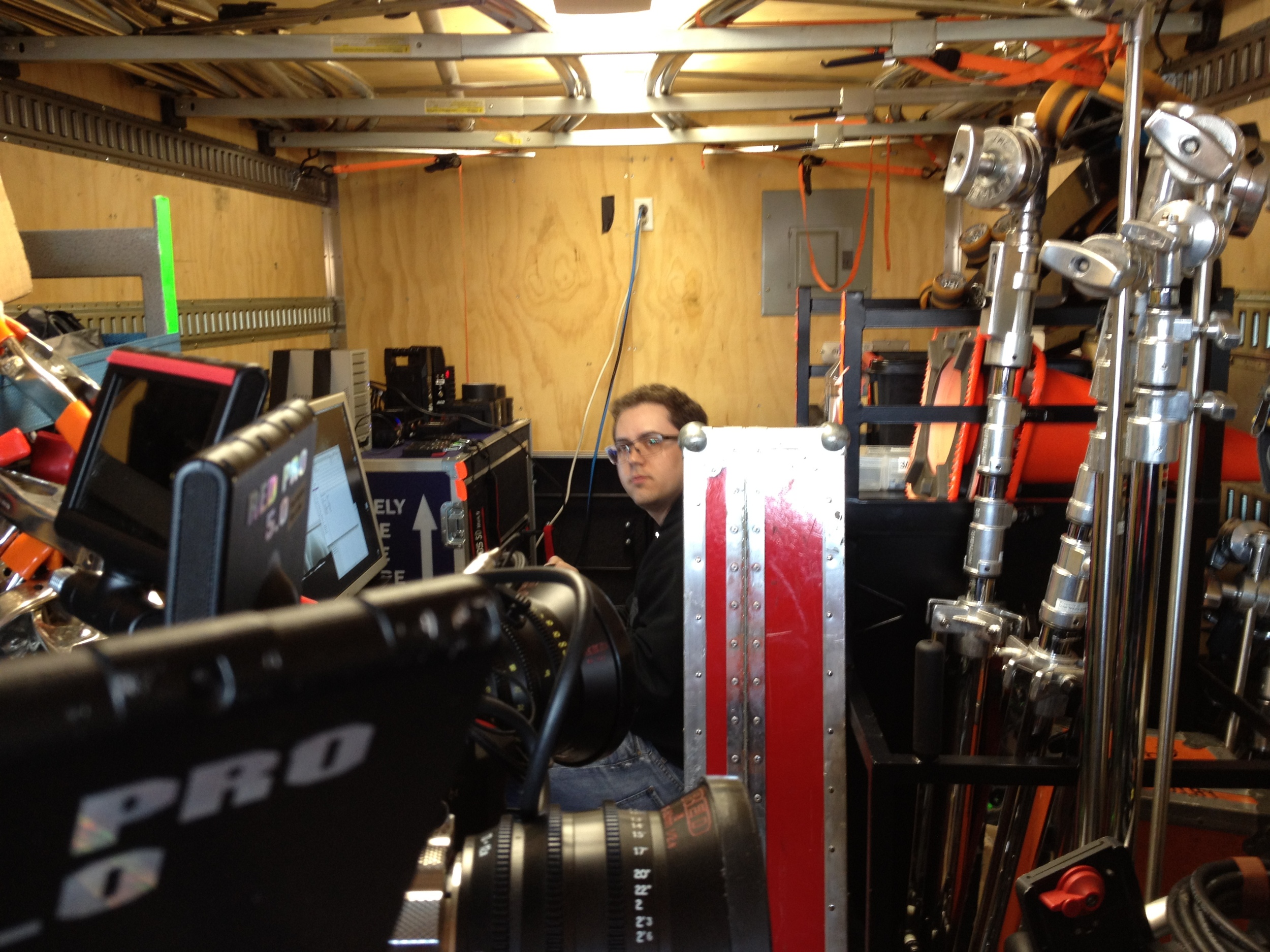
DIT
I was acting as the production DIT and Visual Effects Supervisor. As such, I was responsible for not only backing up footage, but attempting to stitch as many shots as possible while we still had the opportunity to reshoot them should there be an issue with a given setup.
Since nearly all of our prep time went to assembling the camera rig, we didn’t have much of an opportunity to customize our DIT station. I was able to make sure the system arrived with a large e-sata raid, additional e-sata ports for the Red Stations, and a Red Rocket card for realtime processing. The only software I had an opportunity to load aside from AfterEffects was a tethering app for my iPhone, allowing me to download software in the field as needed [8].
This being essentially an “out of the box” Mac Pro, it was outside our firewall and unable to connect to our license server running Nuke. Our composites were to be finished in Nuke, but stitching on site was only possible with our local copy of AfterEffects, resulting in some rework for me later and a few inconsistencies between on-set results and the final composites.
All backups were performed with R3D Data Manager and all dailies were created with RedCine X. For the dailies, I selected the best take of a given setup, and created a full resolution, 5K JPEG image sequence from each camera.
The JPEG sequences were immediately imported into AfterEffects and undistored with the help of the lens grid charts. Since we used limited focal lengths during shooting, I was able to reuse lens distortion data to speed up the stitching process from shot to shot, getting the undistored plates “close-enough” for a quick and dirty composite. Imperfect lens correction was acceptable at this point because stitching on set was only for the purpose of checking parallax errors and determining if we would be able to hide issues in the final composite.
When I felt I had a composite that was good enough and would be easy to finalize in Nuke with a proper amount of attention, I rendered a 3,680 x 540 H264 file to watch (repeatedly) at full screen on the 30’’ Apple Cinema Display. When the Director, Producer, and DP had bought off on the successful stitch, I moved on to the next shot, while continuing to download, transfer, and render in the background. When our four day production ended, we had nearly 4Tb of data, consisting primarily of the raw camera backups.
The largest obstacle to overcome for the DIT work was my physical location. Since we were on a secure construction site with a minimal number of escorts, the most pragmatic location for the DIT station was in the back of the grip truck, traveling with the crew. Our grip truck is equipped with an on-board generator, but this meant I was unable to charge batteries or backup footage overnight [9], and since we had contractors working in our crew, we were held to a strict 10 hour day [10].
Another frustration for DIT work was the cold temperature in the back of the grip truck. If you’ve never been to a desert like Phoenix in the winter, you probably wouldn’t assume the temperature drops as low as it does. Construction shifts begin early and so did we. Our call time each day was pre-dawn and the temperature was in the 30s. The days warmed up around midday, but the shaded location for the metal Mac Pro typically stayed around 50 degrees Fahrenheit.
I bring up the cold mornings not as a complaint about uncomfortable conditions, but because extreme temperatures affect electronics. The DIT station was built into a rolling shipping container, designed specifically for working in the field. That was great for portability, but it made the swapping of components incredibly difficult, specifically the main surge protector that powered the system. Each day, the device that had worked perfectly in our warm office the week before, refused to power up on the first three attempts. On the fourth, the system would boot and remain on all day, but it was certainly a scare that we didn’t need each morning.
Along with the surge protector, the monitor occasionally obscured the images with a snowy noise not unlike an old analog television. My assumption at the time was the graphics card had come loose during travel and needed to be adjusted in its slot. A reboot and a jiggling of the DVI cable seemed to resolve the issue each time it occurred.
In the recent weeks, this system was still exhibiting some odd behavior. After the graphics card was swapped to no avail, the system was sent back to Apple for further investigation. They were able to determine the fault lied with the electronics in the 30’’ Cinema Display, not the graphics card. Additionally, they found a crack in the motherboard of the Mac Pro which occurred on the shoot, proving just how lucky we were to even finish the project.
The Edit
At the time of production, Intel Studios’ primary NLE was Final Cut Pro 7. One limitation in FCP7 is its inability to edit projects with a resolution above 4K. We built a custom project template inside of Final Cut, allowing us to edit in 4K and transfer the project to AfterEffects for finishing at full resolution, but it was overly complicated and introduced many opportunities for failure.
As a result, we took this opportunity to audition Adobe Premiere Pro CS 5.0 as a replacement NLE [11]. Premiere offered us the ability to create a project at our full, final resolution of 7,360 x 1,080. With the aid of another Red Rocket card, the editor was able to assemble the project from the full resolution R3D files.
At the same time, I created EXR and JPEG sequences of the selected panoramic takes and created the final stitched composites in Nuke. Ninety percent of the compositing was done with the JPEG sequences to ease the load on the CPU and our network. This became especially important when we found the best results were generated by using camera re-projection in Nuke’s 3D environment, and photographing the 3D composite at the full 7K resolution. While this technique slowed the compositing process compared to a traditional 2D composite, the time was reclaimed when we were able to reuse the 3D camera re-projection rig, again thanks to our limited number of focal lengths used on set. Before rendering, the JPEG sequence was swapped for the EXR sequence and final color matching of the three cameras was adjusted.
When a shot was completed it was again rendered at 3,680 x 540, this time in ProRes HQ, and scrutinized on a 30’’ computer monitor. Once approved, a 7,360 x 1,080 TIFF sequence was sent to the editor for integration into the video.
How To Build A Better Rig
If we were to attempt such a project again (hopefully with a bit more time and money) I’d be very interested to test the potential use of a Stereo3D beam splitter camera rig.
While it’s certainly not designed for this purpose, using a stereo rig set to zero interaxial distance and adjusting convergence to pan the second camera, I think we could design a panoramic video rig that would be much more forgiving with parallax errors, and create better looking final images. Additionally, if we were able to remove the majority of the parallax errors by getting the sensors closer together, the use of two cameras instead of three might be feasible.
So, How Did It Look?
After all the production hurdles we encountered, I must admit, seeing 160 foot wide, 7K+ panoramic video was beautiful. More importantly, the crowd and the customer loved the video. It’s hard to ask for more than that.
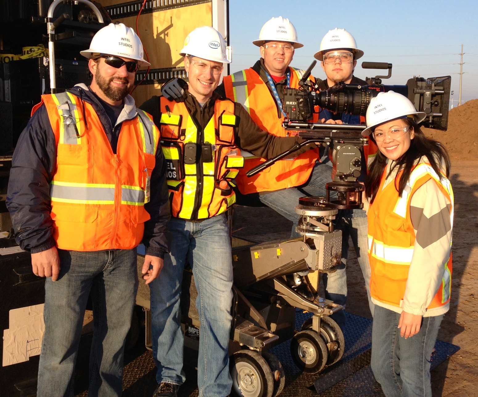
The Crew
By now, one thing that should be patently obvious is that the success of this project was due entirely to our dedicated and talented crew. I would be remiss if I did not recognize them here:
Writer/Director: Roland Richards
Producer(s): Charlyn Villegas, Keith Bell
Director of Photography: Jeff Caroli
1st AC: Josh Miller
DIT/Compositor: Dan Sturm
Editor: AJ Von Wolfe
Music by: Karlton Coffin
And additional thanks are in order for Keith Bell who both commissioned this writeup and offered editorial guidance.
Photo Gallery

-
Intel Studios is an internal media team within Intel® Corporation. ↩
-
In the name of disclosure, I must inform you that, as of March 2013, I am no longer an employee of Intel® Corporation. ↩
-
14 nanometer process technology, to be more specific. ↩
-
For a practical demonstration of how sensor size affects Field of View, check out this awesome web app from AbleCine http://www.abelcine.com/fov/ ↩
-
Technically the Red Epic sensor is slightly larger than Super–35, measuring 27.7mm (h) x 14.6mm (v) versus Super–35’s 24.9mm (h) x 14mm (v). ↩
-
A very long story for another time. ↩
-
We immediately purchased a replacement LCD for the rental house. Sorry Jason and Josh! ↩
-
I do not recommend this solution, even if you have an unlimited data plan. Talk about unreliable. ↩
-
The construction site, until completion, was the property of the construction company. Despite being an Intel facility, we were guests and required to abide by a great many rules regarding safety. Leaving an unattended generator running in a truck overnight was not allowed. ↩
-
When you factor in security briefings, the inability to leapfrog setups, and waiting for construction cranes that cannot be directed, 10 hours is much less time than you’d think. ↩
-
Since development of FCP7 had been abandoned by Apple in favor of the replacement product FCPX, we were already in the market for a new NLE. ↩